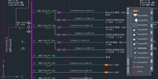
An electrical system diagram is a schematic layout that connects various electronic components like power, resistance, wire, and electrical symbols (voltage, current, etc.) in a certain way. It is applied to indicate the role of each electrical component, their interrelationship, and the electrical working principle. A complete and precise electrical system diagram is key to programming, analyzing electrical circuits, and preventing circuit faults.
ZWCAD has been widely used in the electronics industry, efficiently aiding enterprises like Bosch, Siemens, Zhongheng, Kinwong, and Keyvia. You can accomplish an electrical system diagram easily by employing a variety of drawing and editing commands in ZWCAD. Buckle up — here’s a quick lesson!
Use Block Attribute to create customized component library for easy reuse.
Switches, lamps, and sockets are common components for engineers in drawing electrical system diagrams. Manual work is costly because of the large quantities and varieties. In this regard, ZWCAD provides the Block Attribute function in addition to an existing library of standard parts, enabling engineers to custom component blocks to create their customized component libraries, so that they can store and directly use various commonly used components. It could considerably reduce repetitiveness and enhance the working efficiency.
How? Follow the instructions as below.
Step 1. Open the Tool Palette through [Tools] and click [Tool Palette Window] or use the shortcut command [Ctrl+3] on the menu bar.
Step 2. Select the required component block on the current drawing, then hold down the left mouse button, drag it to the tool palette, and then release it. After that, the block is added to the Tool Palette.
Use Block Attribute and Tool Palette to create and use an electronic components library.
Use Layer to manage layers efficiently and display intuitively.
In electrical drafting, engineers could use multiple layers or colors to distinguish different graphics and symbols. All layers in an electrical system diagram can be classified according to different components, while the same type of layers can be distinguished through setting each layer by name, color, line type, etc.
The classification of electrical layer settings in ZWCAD is shown as below. Usually, when setting layers, you should comply with these principles:
- The fewer layers, the better. You can reduce the number of layers by merging them appropriately.
- Layer 0 is used for Blocks. It is best not to draw other graphics on layer 0.
- You can set different colors, line types, and wireframes for each layer to differentiate graphics.
ZWCAD layers setting classification.
When setting layers, due to quantities of objects on the drawings, graphics may overlap one another. The Layer Transparency function of ZWCAD enables engineers to set the transparency of non-primary entities on the drawing to highlight the primaries.
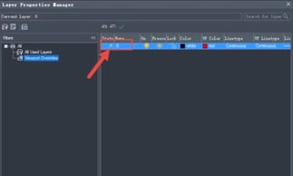
You can set and check the transparency of the entity in the [Transparency] in Layer Properties Manager or the Properties panel. When the transparency type of the object is ByLayer, the transparency value of the object will change with the one of the layer where it locates. In addition, engineers can also use the Viewport Layer to adjust certain layer properties in each viewport for highlighting.
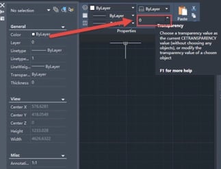
The transparency value of the currently selected entity.
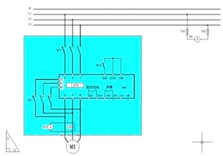
Use color to highlight graphics.
Use color to highlight graphics.
Use ZWCAD Smart Plot to output multiple electronic diagrams all at once.
Electrical system design projects contain multiple drawings — from just a couple, up to a few dozens. Engineers often draw multiple drawings in a DWG file, and manually select them one by one for printing, which is inefficient and cumbersome.
ZWCAD provides an intelligent Smart Plot function to help engineers output multiple diagrams in the same file at one time. The range of frames can be automatically identified according to the layers, the blocks, periphery of the frames, etc., to ensure that the printed drawings are complete and meet the requirements. At the same time, ZWCAD also provides a variety of virtual printers which could directly output other commonly used file formats such as PDF, JPG, EPS, etc., to facilitate the exchange of drawings among engineers.
Follow the steps to use Smart Plot:
Step 1. Open the drawing to be printed, click [File] in the toolbar, and then click [Smart Batch Plot].
Step 2. Select the printing device and choose a [Frame Style] in the pop-up dialog box.
Step 3. Click [Select batch drawings], and select the drawings to be printed.
Step 4. Click [Highlight], and finally click [Plot].
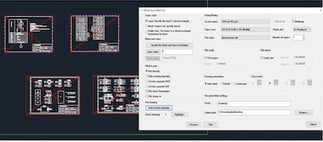
ZWCAD Smart Batch Plot.
Electrical drawing design is complicated, requires consideration of aesthetics, practicality, efficiency, and more. ZWCAD is the 2D CAD platform software competent in stability and compatibility. You can quickly draw and output the electronic diagrams with the help of the functions introduced. Why not give it a try now?
Learn More about ZWCAD
Visit www.zwsoft.com to know more about ZWCAD, a powerful, reliable and DWG compatible CAD solution.
>>Download ZWCAD 2021 and enjoy your 30-day Free Trial!

ZWSOFT CO., LTD. (Guangzhou) is a reliable and innovative engineering software provider with its flagship products ZWCAD and ZW3D. Committed to providing complete and seamless user experience to worldwide users with its all-in-one CAx solutions, ZWSOFT has continuously satisfied diverse needs of various industries such as AEC and MFG. With over 20 years’ experience in the industry, its products and service have been proven by over 900,000 clients across 90 countries.

Searching for more information about Architecture, Infrastructure, & Construction?
Click here!


Share This Post